The Sequence Diagram
- 5 minutes read - 985 words⚠️ Disclaimer
Any kinds of diagrams have nothing to do with TDD at all. We find the diagrams handy when we want to visualize, explain, teach, or learn something. That’s all. It’s a drawing on a sheet of paper that we throw afterward. We don’t keep the diagrams around; we don’t maintain them. That’d be a massive waste of time.
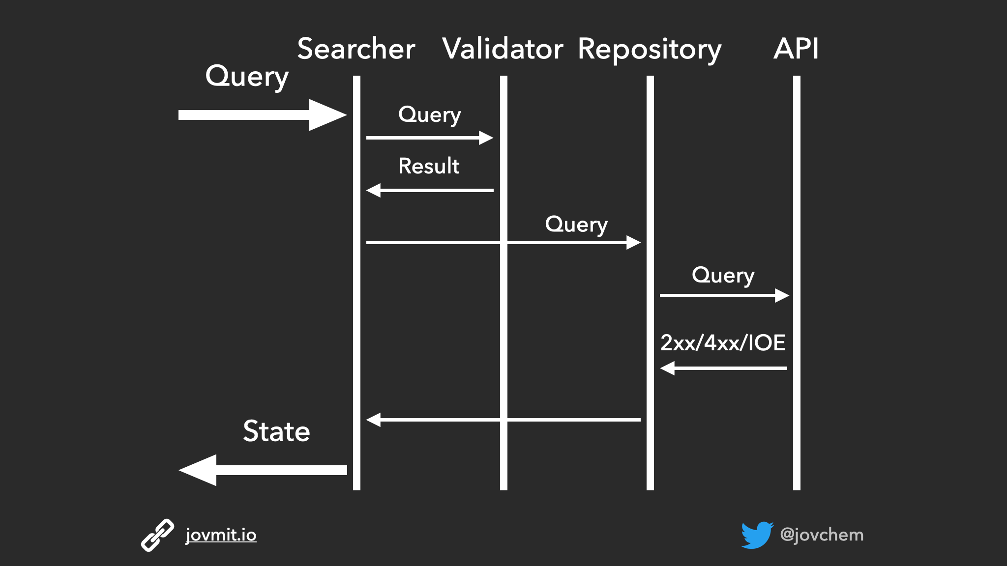
Sequence Diagram Example
What’s this Sequence Diagram thingy?
As mentioned in the disclaimer, the sequence diagram is a tool we can use to visualize an approximation of where we want to go when working on the unit in question. Before we work on anything, we certainly know or have an idea of where to start and where we want to go. The essence of the sequence diagram is to visualize that idea, nothing more than that. I usually draw it on a sheet of paper.
How to utilize it?
The first thing we have to do when coming up with a sequence diagram is to identify the outside of the unit we will build. Let’s look at some examples:
File Downloader
Suppose we are about to build a file downloading feature. In that case, most probably, the input would be some URL where the file exists, and the output would be, for example, the current downloading progress, download success and a possible failure, etc. Next, we would start thinking about different responsibilities this unit will have (like calculation of progress, persisting the progress of the current download, download continuation after a failure, etc.). We would think about splitting these responsibilities into suitable collaborators. We would think about the communication between them.
Follow a User API
Another example would be an API on our REST backend system that we could use to establish a follow between users. So we can start looking at the possible request that we would receive and the response we might return as the outside of the system. Then, we could think about the internals, like the controller that would unpack the request and pass the data into a service that will talk to the persistence, and based on the persisting result, we would form a response and reply it to the caller.
A Search Functionality
The example we would use for the rest of the article is the same example I use in the screencast series I’ve recorded, that you can find in the screencast section. It is a search functionality on a mobile app, so let’s see how to draw a sequence diagram for that particular feature.
Getting started
As we saw in the examples, we start by identifying the outside of the unit we are about to build. In this example, we have a screen that could fire up a query and render state (uni-directional data flow), so we could look at the screen as the outside of the system. The screen has to send the query somewhere, and it has to receive the states to render from somewhere too. In this case, we name the somewhere as Searcher.
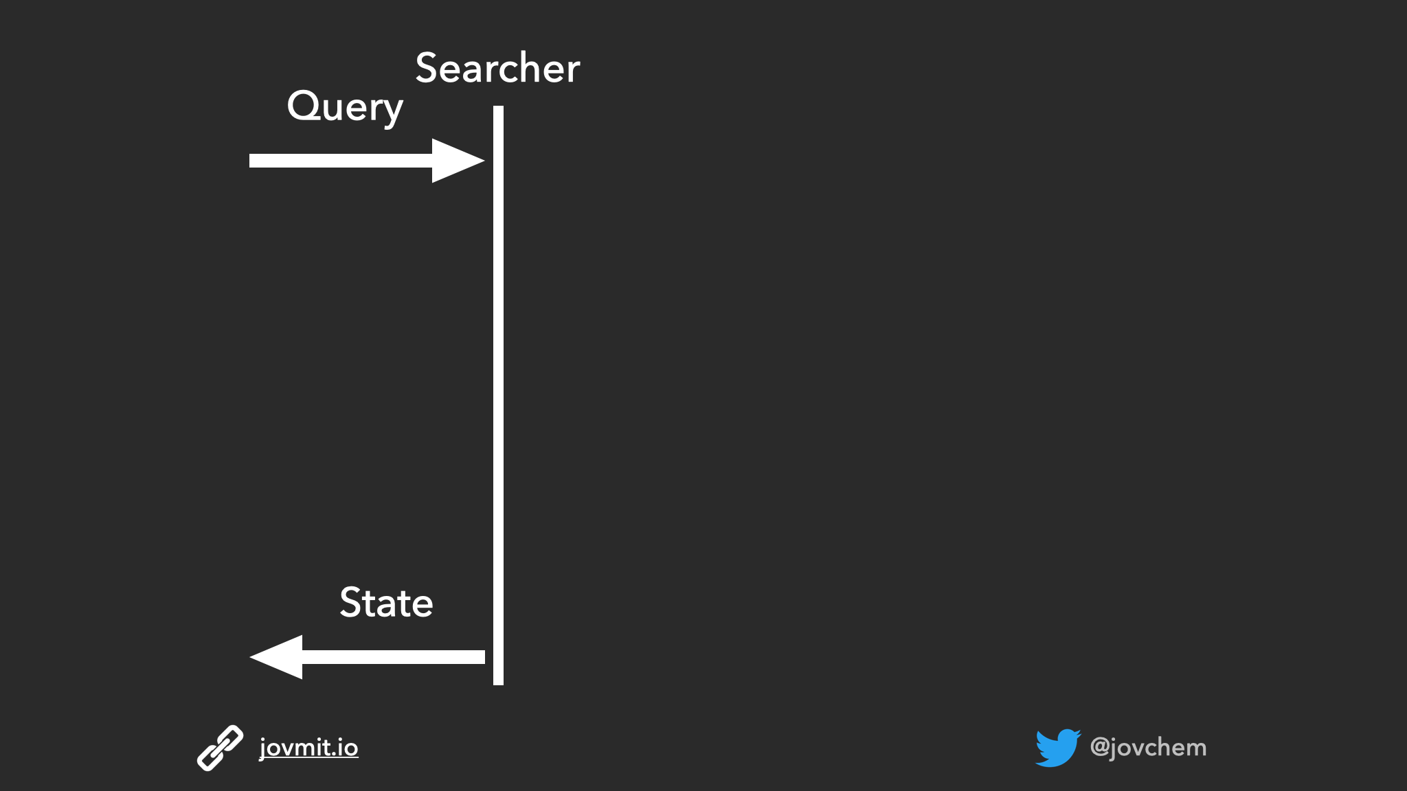
The outside of the search functionality
In terms of mobile, considering the uni-directional data flow is quite handy because it will naturally help us make the UI very simple and not contain any logic inside.
From outside towards the internals
Identifying the outside is the first step towards shaping our Acceptance Test. The AT focuses on the input and the output of our system. Next, we can start thinking about the internals, having in mind the requirements we have in hand. Let’s assume that in our example, we might not perform a search when the query is not valid so that we won’t waste resources. We don’t need to think about what makes the query valid or invalid at this stage, but it’s essential to consider that some validation will happen. We can judge whether it makes sense to make the validation inside the Searcher or distribute that responsibility to a collaborator. Having the validation inside the Searcher will most probably add a reason for the Searcher to change whenever we want to update the validation criteria. Therefore, a better idea is to ask a collaborator to do the validation.
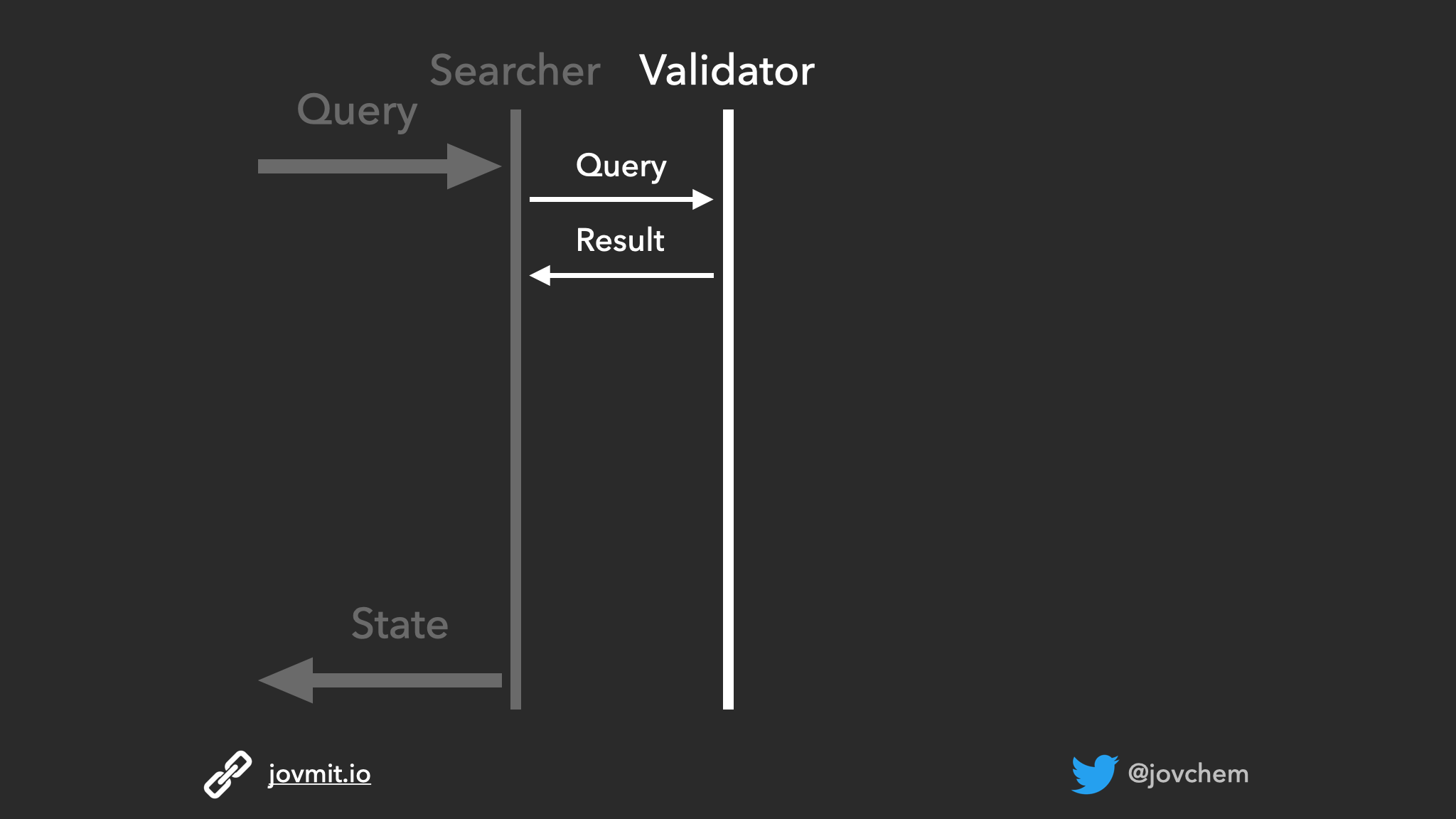
Searcher - Validator communication
Once we have the answer from the validator, we think about the next steps. In case the query is valid, we should do the actual search. So we might pass the query to a collaborator that would perform the search call. Let’s name it Repository.
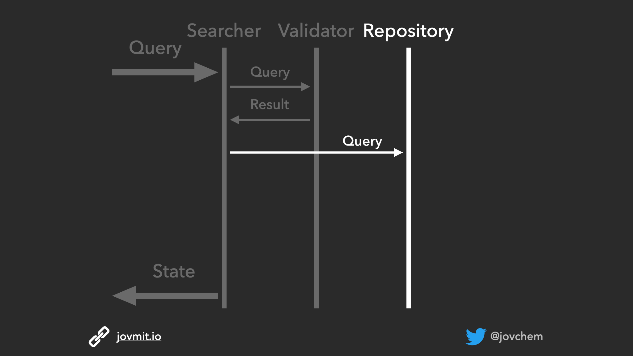
Searcher - Repository communication
Thinking about this new collaborator’s responsibilities, it won’t only have to call an external system, but it will have to deal with the different results (success/error). It might also need to deal with possible data transformations, and then we’ll need yet another collaborator. Of course, it depends on the domain models we might have and the actual response models coming back from the API. For now, let’s don’t overcomplicate things and assume we only do the call and handle the results.
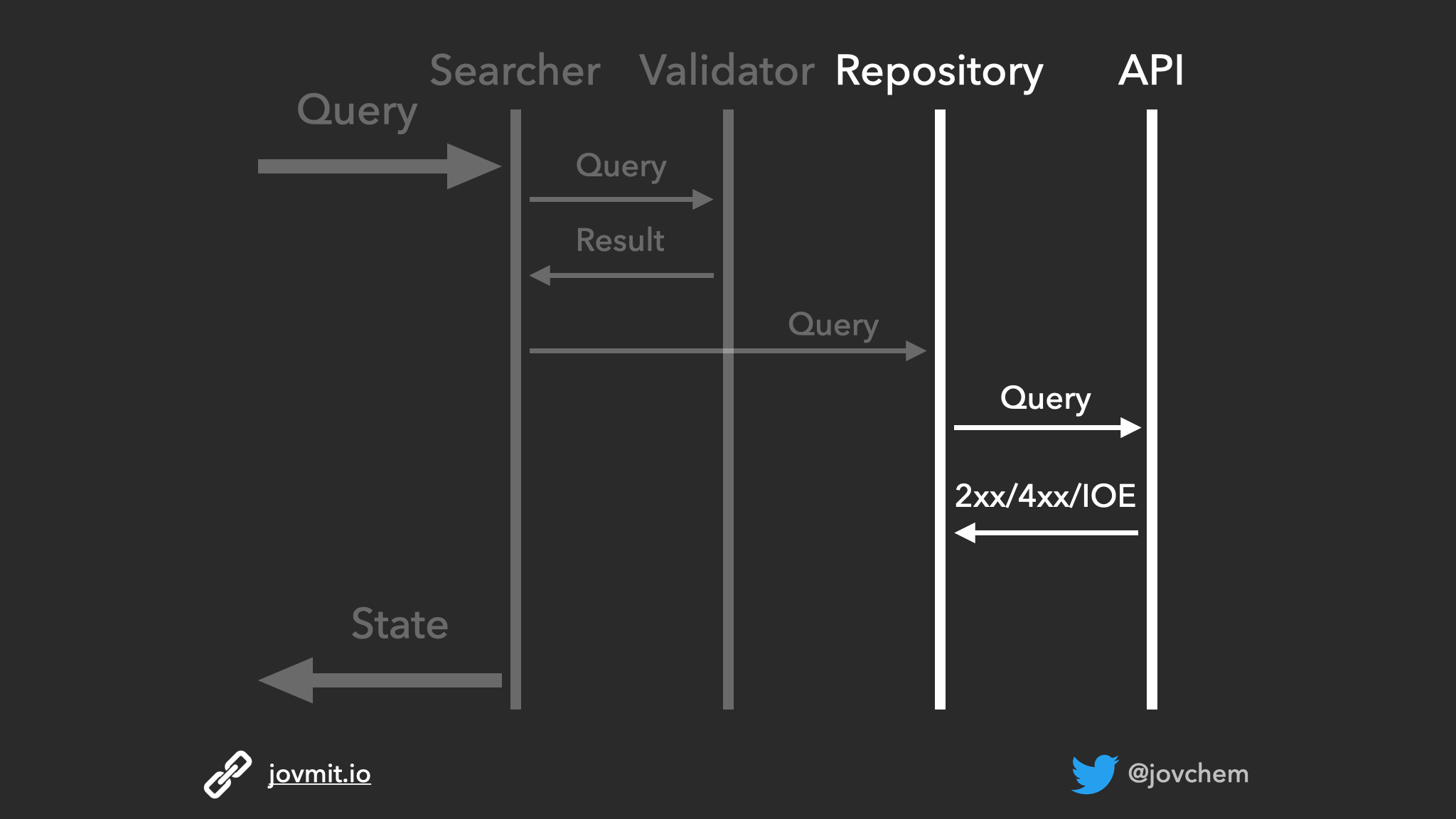
Repository - Api communication
Once we have the search call results ready, we need to return them to the Searcher. Then, they’ll get delivered to the UI as a state to render.
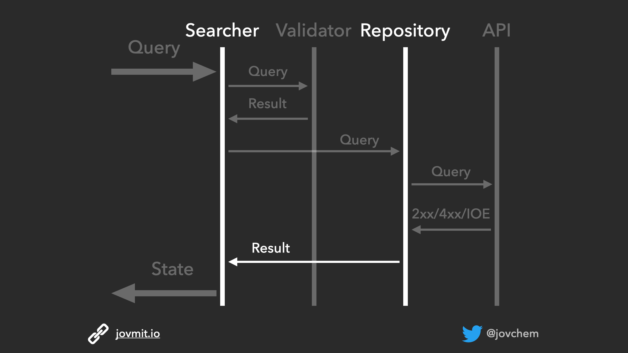
Repository - Searcher communication
Defining too many details
As we described earlier, the sequence diagram should be a visual approximation of the unit we want to build, and it would not involve details like the data types that are going to be involved. It’s fair to think and come up with ideas, but they will emerge later when we start with the implementation.
Screencast
Here is the first episode of the series where I demonstrate the practical work on the search functionality. It focuses only on the sequence diagram. In the following episodes, I present how to use it to help us out move forward.
Consider subscribing on YouTube and following me on Twitter so you will stay up to date with new content.